
TODO

The Core Processor is a 1 GHz Cortex-A9 processor built by TI.
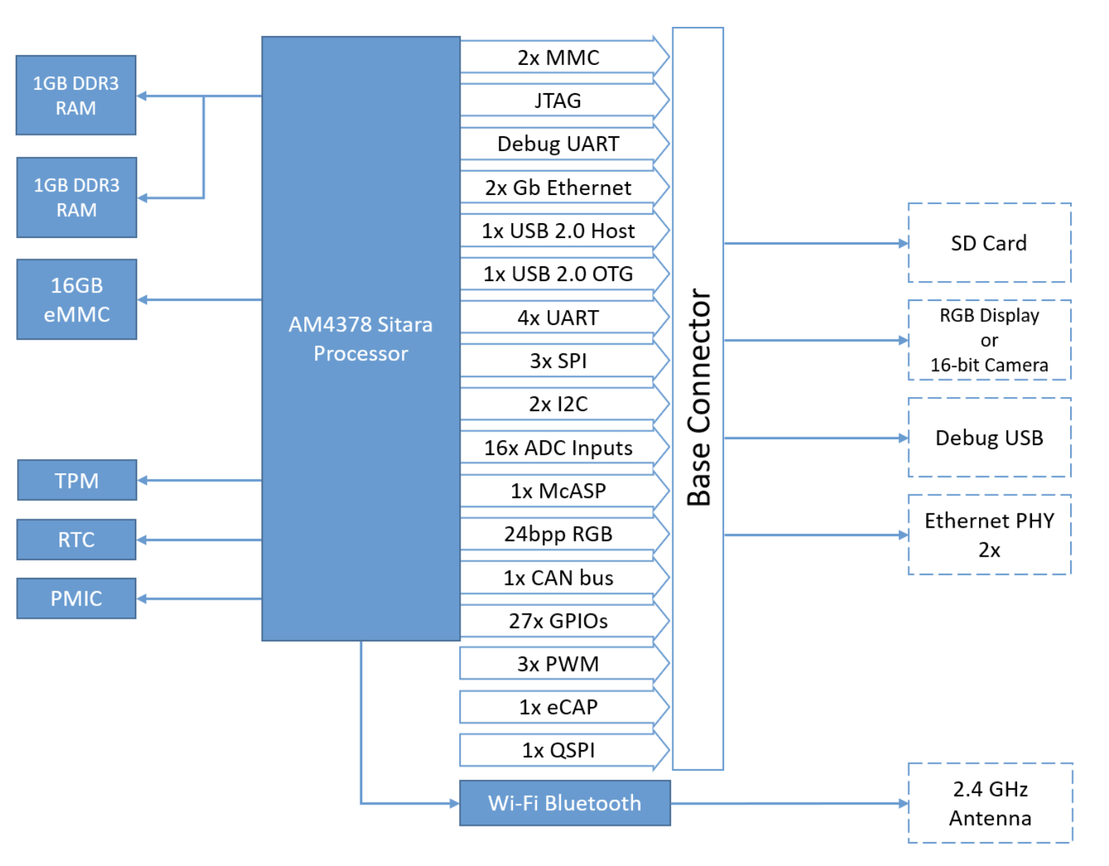
The base Interceptor Module comes with 1 GB of DDR3 RAM.
The base Interceptor Module comes with 8 GB of eMMC flash. This contains the bootloader and OS images and can be used for data storage and other application images.
The TPM chip is an encrypted hardware key storage module that supports the TPM 2.0 specification from the Trusted Computing Group (TCG). This chip can be used for Device Provisioning and Key Management.
The Realtime Clock provides a hardware-backed time clock.
The combined Wi-Fi and Bluetooth Interface uses an ESP32 Chip over SDIO. This interface can be configured to act as both a Bluetooth host or peripheral or as a Wi-Fi client or Soft Access Point.
The on-board Power Management IC controls the module’s voltages and basic power-down functionality. This can be configured via a dedicated I2C interface.
The processor’s Display Subsystem (DSS) outputs a 16 bits per pixel RGB/TTL signal that is then transformed into an HDMI output on the QuarterMaster. This can be used to drive mid-resolution displays and HMIs.
The serial debug console is accessible through the micro-USB port on the QuarterMaster. This allows access to the boot-up process and core device configuration when enabled.
The JTAG debug interface is exposed on the QuarterMaster using the standard 20-pin ARM connector.
4 USB 2.0 device ports are exposed via an on-board USB Hub chip on the QuarterMaster. This device is configured automatically on boot and should recognize devices through the standard UDEV interface.
The Micro USB OTG port is located on the side of the QuarterMaster and can be used in both a peripheral or host configuration.
The Interceptor’s RGMII bus is connected to a Gigabit Ethernet PHY on the QuarterMaster and can be configured in Base 10/100/1000 modes.
The QuarterMaster exposes 2 I2C buses with I2C2 connected to the Temperature Sensor and HDMI EDID interface. This interface can operate up to 400 kHz.
I2C is a serial interface that uses two signals: SDA and SCL, Serial Data and Serial Clock, respectively, to communicate with board-level peripherals. Additional sensors and devices can be connected to the same bus as long as the new device addresses do not overlap with any of the devices on the bus.
The QuarterMaster exposes 3 SPI buses with SPI2 connected to the 3D IMU. This interface can operate up to 48 MHz.
SPI is a serial interface that uses 3 primary signals: MOSI, MISO, and SCLK; Master-out-Slave-in, Master-in-Slave-out, and Serial Clock, respectively. In addition, for each device on the bus, a single (typically) active-low Slave Select or Chip Select (CS) line is required to start communication with the peripheral.
The QuarterMaster provides 3 UART Serial Interfaces with UART1 and UART3 exposing the RTS and CTS control lines. These interfaces can operate up to 3.6864 MHz and support the full range of possible serial baud rates.
The QuarterMaster provides up to 21 General Purpose Input/Outputs operating at a voltage level of 3.3V through the on-board edge connectors. Additional GPIOs are included via the Expansion and Feature Connectors. These pins can be software-configured as Inputs or Outputs with processor-integrated internal pull-ups and pull-downs. Full specifications on the different configurations can be found in the AM437X Processor Datasheet.
The QuarterMaster exposes up to 16 ADC Inputs via the Expansion Connector operating at a 0-1.8V range. These ADC inputs are organized into 2 ADC banks: ADC0 and ADC1, and can each be configured with different sample rates up to 1 MSps (Mega-samples per second) and trigger mechanisms.

The Processor SDK Linux Installer (ti-processor-sdk-linux-[platform]-<version>-Linux-x86-Install.bin) will install the necessary components to start your development on the processor. The SDK consists of source for the Matrix App launcher starting point application, a development filesystem, a target filesystem, example applications, toolchain and board support package, ease of use scripts and documentation. The Processor SDK Linux now includes the ARM GCC toolchain. The Processor SDK Linux was built and tested against a specific Linux Distribution name and version, Ubuntu 16.04 or 18.04. Note this does not prevent the user from installing the SDK on other Linux distributions.
NOTE: If you are having trouble running the above commands then you are probably running a 32-bit version of Linux, whereas the installer is 64-bit and will not execute properly.
After the installation refer to section Building Linux for next Steps
TODO The U-Boot source code is included in the SDK’s board-support directory.
Yocto
Ubuntu
Debian
TODO How to configure the toolchain (gcc/g++, linker, etc.) for building basic C/C++ applications
TODO How to deploy a c++ app via SFTP, configure Ethernet, etc.
sudo apt-get install minicom
